Header1200x385

facebook_page_plugin
× If you are studying for your BAK or PPL exams and need some help, please post your question here. Someone on the forum is bound to help you as soon as they can.

Aircraft Trim Sheet loading

  • John.Heddles
  • Offline
  • ATPL/consulting aero engineer
  • Posts: 843
  • Thank you received: 101

John.Heddles replied the topic: Aircraft Trim Sheet loading

First, this thread goes way beyond what the PPL/CPL student needs to know. It is only here to answer some questions raised by the OP. So, please, don't get concerned if you don't follow all of it. Very much "nice to know" stuff unless you fancy giving yourself a head start with an operator by learning enough to do the weight and balance system designs for the operator - some pilots certainly have gone down this path to their advantage. As I have observed elsewhere, nothing overly difficult here, you just need to be a bit careful and pay attention to detail with what you are doing.

Might just as well show the details for the tick line sloping graphic. Looking at the graphic labelled "tick lines" and starting from the top line -


(a) top line - stock standard tick line trimline as in the Alpha loading system

(b) second line - tick line normal use has an error at the start (estimating the proportion of the tick line at the starting point) and an error at the end (estimating where to stop the horizontal trim IU change)

(c) third line - a simple draughting trick can help with the first error. The trick is to introduce sloping lines which just overlap the tick interval length - the overlap ensures that the drop line has to intersect with a sloping line. By convention, the slope is such that the drop line "bounces" in the correct direction (left or right) to assist with minimising errors. The ticks are removed from the bottom line and an horizontal line added to the top .. just to make the thing a bit prettier.

(d) fourth line - now, when the dropline comes down, it has to hit a sloping line and we can then move in the appropriate direction to run the IU adjustment calculation for the weight change

(e) fifth line - what this sloping graphic does, in effect, is slide the tick lines (up and) across ... resulting in a means of "moving" the tick lines left or right to get the desired result. The final IU adjustment horizontal line is then no different to the basic tick line use.

Now, looking at the fuel grid graphic, labelled "AN 1"


(a) I've included the "hidden" IU scale between the two fuel graphics

(b) if we enter the fuel line graphic at, say, 20,000 kg fuel load we find an IU change, due to the fuel, of around -200 IU.

(c) in the righthand graphic, the red line shows the standard use sequence

(d) if we refer the IU change to the top IU scale, we find the same -200 IU change due to the fuel load.

(e) in effect, the lefthand graphic is just a graphical lookup table to find the IU change, which is then, graphically, added/subtracted in the main trimsheet part of the document. In fact, some sheets actually use a table rather than the lefthand graphic and then the IU change is manually transferred to the trimsheet calculations .. strange way to do things in my view, but you may see such sheets later on.

Now, looking at the graphic labelled "AN 2"


I've done some crossplotting to recast the Ansett sheet fuel calculation into the style used in the TAA sheet. The righthand fuel scale is arbitrary, one line is plotted and then the others are just duplicates of the first. Comparing this with the TAA sheet, you will see that the two sets of lines are much the same (ignoring the second baggage compartment auxiliary fuel tank in the 200LR version)

Any further questions, please do put them in for discussion.

Engineering specialist in aircraft performance and weight control.
#11
Attachments:

Please Log in or Create an account to join the conversation.

  • rhlmcg101
  • Topic Author

rhlmcg101 replied the topic: Aircraft Trim Sheet loading

Thanks, it's all helping my understanding the discussions I had with my colleague some time ago. A question - I can't work out how you did the plotting in your jpeg AN2. Can you show a little more in the detail to help, please ?
#12

Please Log in or Create an account to join the conversation.

  • John.Heddles
  • Offline
  • ATPL/consulting aero engineer
  • Posts: 843
  • Thank you received: 101

John.Heddles replied the topic: Aircraft Trim Sheet loading

The confusion probably arises from my plotting the second graphic overlaying the first when, in fact, the two are independent. If I separate them, it may make things a tad clearer ..

Reference graphic AN 03 ..


(a) I've moved the TAA style graphic down so that it is separate from the AN style graphic.

(b) the first line is drawn

(c) a sample plot position at 22,000 kg fuel load is shown.

(d) on the AN style graphic, the fuel line results in an IU change of about -260 IU as can be seen on both scales

(e) on the TAA style graphic at the bottom of the jpg, the co-ordinate plotted is 22,000 kg and -260 IU.

(f) on the final graphic, the first line is duplicated and positioned to suit several times as shown in the previous post. As indicated previously, the use of this style requires that the family of fuel lines be used as guidelines to obtain the IU change for whatever ZFW dropline position comes into the carpet.

Engineering specialist in aircraft performance and weight control.
#13
Attachments:

Please Log in or Create an account to join the conversation.

  • rhlmcg101
  • Topic Author

rhlmcg101 replied the topic: Aircraft Trim Sheet loading

Thanks a lot for that. Things are becoming clearer.

My colleague has been overseas for the past few weeks but will be back later this week when I expect to be able to get the other sheet to post.

In the meantime, can I ask a couple of extra questions.

Question 1 For the Ansett and TAA trimsheets, why are the starting line IU values so different ?

Question 2. Some manufacturers use a cg envelope like the Cessna 310 posted. Can you explain what this presentation achieves please

#14
Attachments:

Please Log in or Create an account to join the conversation.

  • John.Heddles
  • Offline
  • ATPL/consulting aero engineer
  • Posts: 843
  • Thank you received: 101

John.Heddles replied the topic: Aircraft Trim Sheet loading

For the Ansett and TAA trimsheets, why are the starting line IU values so different ?

The generic formula for a trimsheet IU is

IU = C1 + [(FS - TD) * Weight] / C2

where

C1 is a constant chosen simply to get rid of negative numbers along the top IU entry data line ie it can be any value the designer fancies.
FS is the CG of interest measured in OEM fuselage station units
TD is the datum chosen for the trimsheet, again measured in FS units. The value usually is referred to as the trim datum, or similar.
FS-TD simply refigures the arm for the IU equation from the TD position rather than from the OEM FS zero position
C2 is the usual constant to convert moments into IUs.

Considerations

As I don't have either the 200 or 200LR weight and balance manuals to hand and it doesn't add much to the discussion, we will have to leave C2 as an undefined number (simply to spare my having to do a bunch of research to get sufficient data to figure it out for no great value)

Both sheets look to have the trim datum chosen to be at around 30.5% MAC and appear to use the same value for C2. As a result the IU scales are similar other than for the starting points.

The TAA sheet uses C1 = 100 while the AN sheet uses C1 = 0. This is the main driver for the IU lines' appearing to be quite different. In fact, they are much the same for the purposes of the trimsheet calculations. The C1 value has no effect on the actual IU calculations and ONLY gives a different number for the IU entry.

Some manufacturers use a cg envelope like the Cessna 310 posted. Can you explain what this presentation achieves please


The short answer is that the presentation simply gets around the graphical problems of the typical OEM datum up around the nose somewhere. This usual position results in a thin, sloping CG envelope (in weight x moment or IU format) which reduces plotting and reading accuracy. By a simple graphical change the chart can be drawn with a much wider forward to aft limit at each weight which greatly improves plotting and reading accuracy.

Although the presentation could be used for a trimsheet (a bit messy and no-one would bother doing so) may I suggest that you repost that specific question as a separate thread so that anyone who might be looking for a similar answer in the future has a better chance of finding it. I can then post the long answer to the question.

Engineering specialist in aircraft performance and weight control.
#15

Please Log in or Create an account to join the conversation.

  • John.Heddles
  • Offline
  • ATPL/consulting aero engineer
  • Posts: 843
  • Thank you received: 101

John.Heddles replied the topic: Aircraft Trim Sheet loading

This post is a copy of that in the other thread www.bobtait.com.au/forum/rpl-ppl/5255-cg-envelope with a bit tacked on at the end relating to the trimsheet considerations.


I guess we should satisfy folks that the POH presentation you have cited is just a rework of the typical CG envelope (as weight x moment or IU) that everyone is used to.

First, let's draw a CG chart using the OEM data in the usual format. Choose some convenient scales to suit .. doesn't matter what you choose.


This should look much the same as your typical small single engine trainer envelope from most GAMA style POHs.

Now let's overlay the present POH chart with the standard version.


As can be seen the scales in the two graphics don't line up so we need to tidy that up a bit.

With reference to the following graphic, what I have done is


(a) rescaled the standard graph vertically to match the POH chart. (In effect, we just squeeze the chart vertically to fit).

(b) stretch the standard graph horizontally to match the POH chart. In particular, in this case, I have made the bottom vertices (forward and aft CG) the same scale length

(c) position the standard graph over the POH chart as shown by the two blue circles

Next, if we skew or shear the standard graph as we might do with a deck of cards, we can change the appearance of the standard graph to align nicely with the POH chart. A bit of tidying up and we could, quite easily, have drawn the POH chart from scratch.


The original POH chart almost certainly would have been drawn on the board by a draughtsman using a draughting machine (not many folks still use those these days, I suppose). These days, one could do it either the way I have shown above (in a vector graphics or CAD package) or just go straight to the end result and plot it directly (either in a package or on the board, according to one's preference). The skew angles are pretty standard to get a nice final presentation so there is not much in the way of imagination required.

Now, what does this presentation achieve ?

The standard envelope, using the typical OEM datum position, generally results in an elongated graph which is characterised by a small physical distance between forward and aft CG limits which reduces both reading and plotting accuracy. For this aircraft, the datum is the main jack pad position which doesn't accentuate the problem as much as one sees with datum positions, say, up near the nose.

While maintaining the OEM standard datum position, what the POH chart has done is stretch the forward and aft CG distance on the graph. As a result, the chart is easier to use and provides improved accuracy both for reading and plotting points when compared to using the typical standard CG presentation.


Trimsheet considerations

This style of POH presentation can be used in a trimsheet but at the cost of being a bit messy. As a trimsheet is drawn to a vertical background scale of IU, all we have to do is rotate the chart so that the IU scale lines are vertical as, for instance -


However, the weight scale now presents some layout difficulties for labels. For the supposed benefit of keeping with the OEM datum, the use of this presentation in a trimsheet is just not worth the effort when there are preferable alternatives.

It probably is of general readership value to look at the practical trimsheet alternatives in my next post.

Engineering specialist in aircraft performance and weight control.
#16
Attachments:

Please Log in or Create an account to join the conversation.

  • John.Heddles
  • Offline
  • ATPL/consulting aero engineer
  • Posts: 843
  • Thank you received: 101

John.Heddles replied the topic: Aircraft Trim Sheet loading

Following on from the previous post, I made a comment that the OEM datum is not always the best option. This comment only applies to graphical loading system CG charts drawn to weight x moment (or IU) scales.

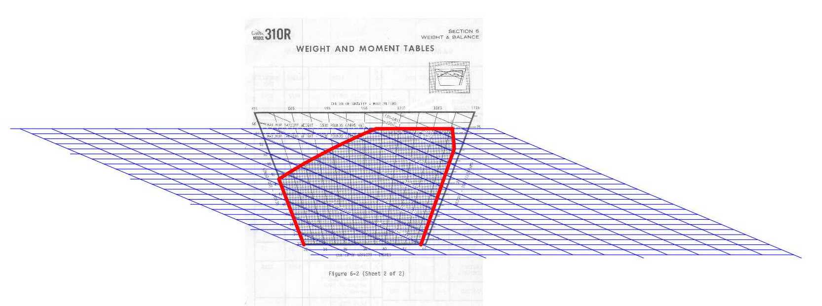
First, let's look at the usual weight x CG scale envelope -


I have drawn the weight x CG envelope with respect to three datum positions, viz., FS -100 (front of the nose cone), FS 0 (OEM standard datum), and FS 40 (back towards the rear CG envelope limit FS).

As you can see, quite easily, the CG envelope graphic is identical for each case, the only change being to the CG scale. Hence the often seen comment that the datum chosen doesn't make any difference - to the CG distance measure - this last bit, usually, is left out, unfortunately.

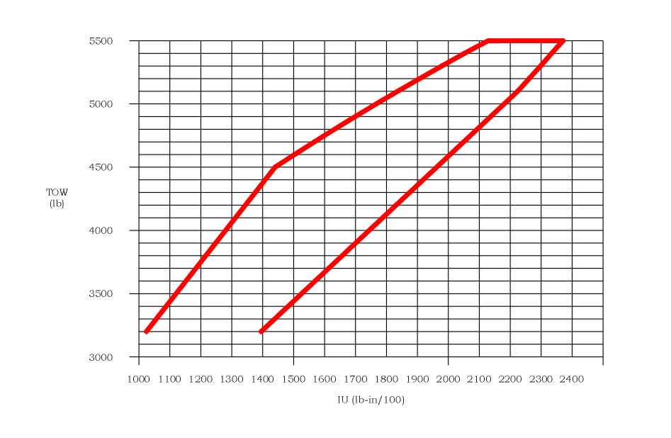
For reasons of calculation/execution simplicity, it is useful to use a CG envelope plotted to scales of weight x moment (or IU).

Note that the two provide THE SAME INFORMATION, other than for the fact that one talks about CG as a distance while the other talks about CG as a moment (or IU). Just two ways of looking at the same thing ...

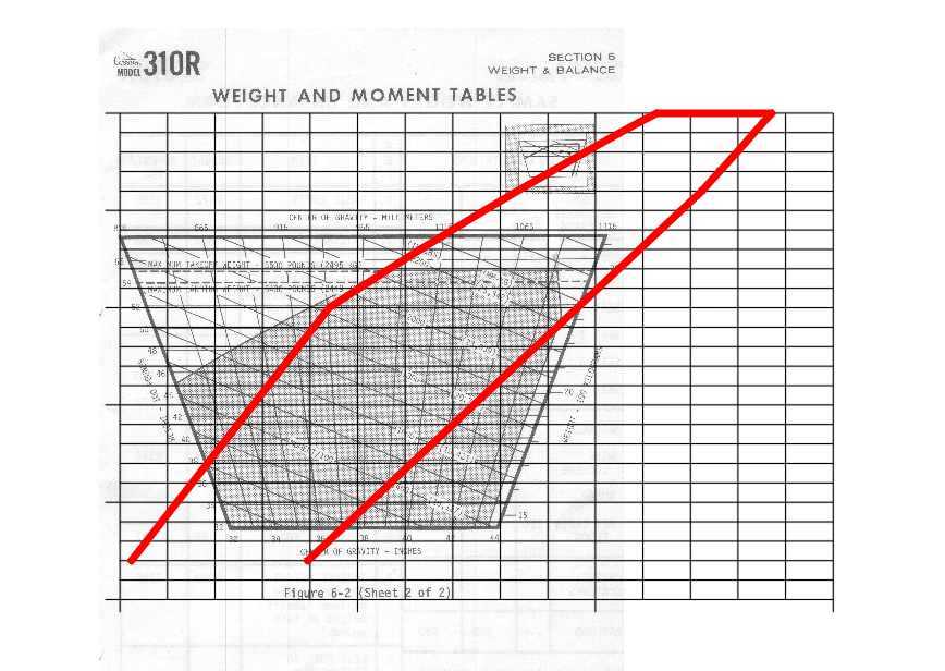
Now, the datum has a significant effect on the plotted envelope -


As can be seen, the choice of datum rotates the plotted envelope -

(a) if the datum is out to the nose, somewhere, the envelope slopes bottom left to upper right (blue line).

(b) if we move the datum back towards the rear of the aircraft, say at the MJP position (FS 0, in this case), the envelope begins to rotate in a manner which causes it to become more upright (orange line)

(c) if we move the datum further back, say into the CG envelope range (in this case FS 40, which is near to the aft most limit CG), the envelope rotates further and, effectively, becomes more or less vertical (red line).

Now, previously, I made a comment that the datum affected the accuracy of plotting and reading off CG points. Looking at this chart, that seems a bit odd as the various envelopes are much the same in dimensions.

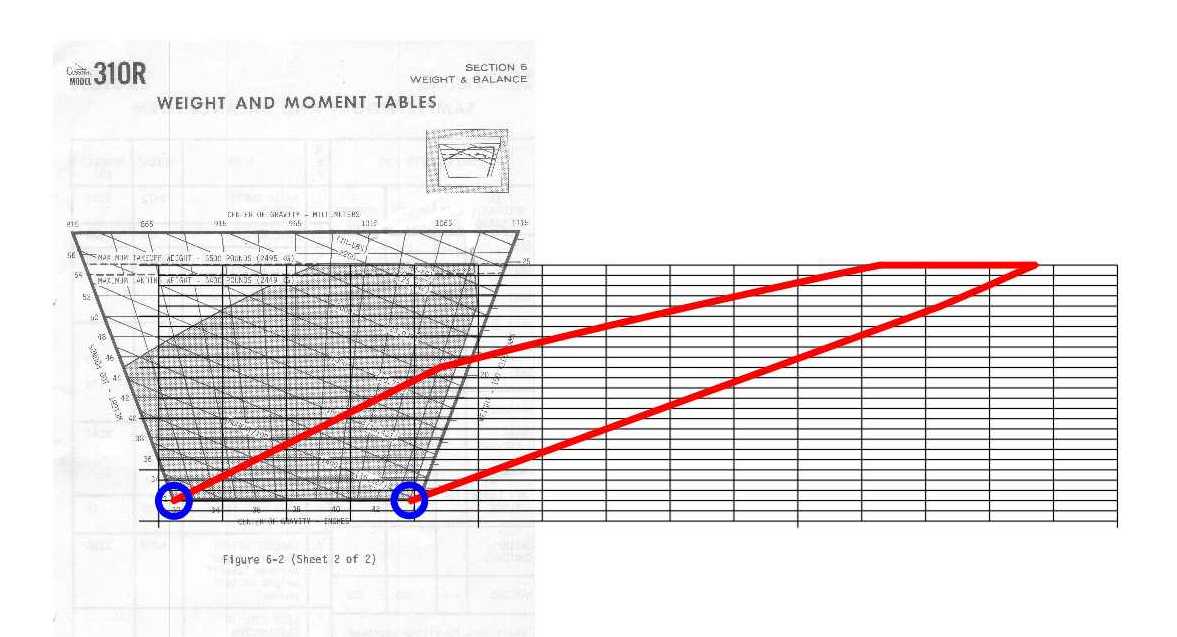
So, let's try a bit further. This time, we will look at the problem from the point of view of drawing the envelope on hard copy (ie a piece of paper, typically A4 through to A3, in current formats). When we do this, we end up having to assign a specific bit of area on the paper for drawing the envelope. In the following graphic, I have drawn all three envelopes on the space allowance, in each case, stretching/compressing the original graphic to fit the space allowed to the maximum extent practicable -


Now, it becomes very evident how the accuracy consideration varies with the datum selected. Which envelope would you reckon provides the best accuracy for plotting and reading CG co-ordinates ? Clue - the fat, red envelope. If you didn't select the fat, red envelope, do go back and have another think about the question.

Note that, with the development of the ubiquitous PC, laptop, etc, etc, with lots of significant figures in floating point calculations, there is no advantage in using other than the OEM datum for longhand (ie computer) calculations.

However, for graphical solutions, the situation still requires the use of a non-standard datum (somewhere inside the envelope limits) to get the maximum accuracy. While the small aircraft end of the market ignores this (except for the use of the skewed envelope, described previously), the larger aircraft market usually has two OEM datum positions defined - the first being similar to the GA FS envelope, and the second (usually called the trim datum, or similar) being defined for loading calculations. The reasons are given in this thread. Note that there is no requirement for the loading system designer to use the OEM datum so it is always necessary to be careful doing anything other than what the designer's instructions require (unless you know what you are doing, of course).

The good designer will select a trim datum somewhere inside the envelope, modified to suit any particular need for the aircraft in question. My light aircraft GA trim sheets, for instance, standardise on the aft-most envelope CG limit unless there be a very good reason to choose otherwise. Other designers may have their own philosophies.

The general rule is that, for a graphical loading system, the envelope should look like a boxy-type shape, such as the graphic for FS 40, above. If you see an envelope, as you will, looking more like the FS -100 example, above, then you may infer that the design is sub-optimal so far as user accuracy is concerned.

If you work your way through this thread, and understand the bulk of it, you will know the majority of what there is to know about graphical loading systems and trim sheet systems, in particular. That can be only a good outcome as you encounter these systems in your GA flying .. and, for those who progress to larger aircraft, that side of the Industry, as well.

Engineering specialist in aircraft performance and weight control.
#17
Attachments:

Please Log in or Create an account to join the conversation.

  • John.Heddles
  • Offline
  • ATPL/consulting aero engineer
  • Posts: 843
  • Thank you received: 101

John.Heddles replied the topic: Aircraft Trim Sheet loading

Another couple of points, following on from the previous post -

(a) if you look carefully at the upper forward envelope line (especially on the red graphic, in which the effect is a bit easier to see) you will note that the line is NOT straight but is curved. Although it is not feasible to see at this scale, the same applies to the upper aft envelope line. This will apply to any line on the weight x CG envelope which is not either horizontal or vertical.

On many occasions, the designer will linearise the line (ie ignore the curve and make it straight by joining the two end points) to simplify the drawing. This needs to be done with care - most times linearisation is conservative (ie one loses a bit of the envelope but remains within the TC envelope). This is the case for this envelope. For some envelopes, however, the practice can be non-conservative (ie the straight line is OUTSIDE the TC limit line) and linearisation must not be used. The problem, of course, is to know which is which and, unfortunately, some loading system designers are not quite up to speed on the details.

(b) a well-designed loading system will address any errors which may accrue from the design of the loading system and actual loading practices. This, usually, is done by constraining the envelope limits (as shown on the loading system) so that the errors don't cause the actual CG to be located outside the TC envelope. The process, usually, is referred to as "curtailment", especially in US practice. The only real problem arising is that a calculated takeoff/ramp CG (often shown as %MAC) will have a small error. However, as the CG is used for setting takeoff trim and a small error is not of practical significance, such an error is acceptable.

Engineering specialist in aircraft performance and weight control.
#18

Please Log in or Create an account to join the conversation.

  • rhlmcg101
  • Topic Author

rhlmcg101 replied the topic: Aircraft Trim Sheet loading

Boy, this thread is ending up like a piece out of a text book.

Some more questions to clarify a few things -

1. You made a comment that a pilot might end up "learning enough to do the weight and balance system designs for the operator". What would be involved in that and how much use would it be ?

2. On trimsheets with sloping tick lines, I have seen a few where the sloping lines do not overlap. What is the significance of this ?

3. In your post number 17, in the second picture you make the statement that "if the datum is out to the nose, somewhere, the envelope slopes bottom left to upper right (blue line)." I see the envelope going from bottom center to upper right. What am I missing here ?

4. In the same picture, what would happen if the datum was moved further toward the aircraft tail ?

5. In the next picture, you seem to alter the various envelopes as you want. Won't this cause problems with the equations ?

6. In the next post, you say that some of the envelope lines are curves and some straight. Why does this happen ?

7. You then say that care must be taken with using straight lines to simplify the curves. Can you give an example when there would be a problem doing this ?
#19

Please Log in or Create an account to join the conversation.

  • John.Heddles
  • Offline
  • ATPL/consulting aero engineer
  • Posts: 843
  • Thank you received: 101

John.Heddles replied the topic: Aircraft Trim Sheet loading

1. You made a comment that a pilot might end up "learning enough to do the weight and balance system designs for the operator". What would be involved in that and how much use would it be ?

Such a pilot would need to get up to speed on the ins and outs of loading system design.

There is no specific need to obtain a weight control authority, although the operator would need to get a suitable WCO (possibly whoever does the aircraft weighings) to check and approve the pilot-developed system. Alternatively, the pilot could jump through the hoops and get an authority and keep it all in house.

As a matter of interest, the present authorities are geared to weighings rather than the development of the more complex loading systems. CASA is looking at whether there needs to be a change to the system, specifically to address the need for the more complex loading system design approvals.

At present, the system appears to sort of cover the need by including suitable words in the WCA issued to the WCO and tailored to the demonstrated competence of the particular WCO. This CASA undertaking is being driven by the major airlines' need for the tech service engineers who do the weight control work to be able to do so without needing a largely irrelevant WCA driven more by light aircraft GA needs. As an aside, it bites both ways .. I have seen very competent airline weight control folk get themselves into all sorts of bother with small aircraft due to having no real knowledge of the different problems existing between big and small aircraft .. but that's another story.

How much use ? .. how long is a piece of string ?

Given that a complex loading system might cost the operator several thousand dollars to have developed by a contract weight control officer (depending on the Type and configuration), keeping it in house with an already-on-the-payroll pilot might be attractive. More importantly, the utility of the loading system can be tailored to the perceived needs of the operation by a currently operating pilot. I have seen more than a few systems developed by technically competent non-pilots which aren't all that nice to use.

On another tack, the operator can also use the relevant pilot to run weight control audits for the operation as part of the SMS etc.

2. On trimsheets with sloping tick lines, I have seen a few where the sloping lines do not overlap. What is the significance of this ?


Similarly, I have seen the same sort of problem. Makes the sheet less useful to use as the drop line may not intersect a sloping line which is the aim of the technique. I suggest, probably, such an observation indicates a lack of understanding of what the technique is trying to achieve .. ie a lack of technical competence on the part of the designer.

3. In your post number 17, in the second picture you make the statement that "if the datum is out to the nose, somewhere, the envelope slopes bottom left to upper right (blue line)." I see the envelope going from bottom center to upper right. What am I missing here ?

4. In the same picture, what would happen if the datum was moved further toward the aircraft tail ?


Let me run up a graphic and come back on these two questions.

5. In the next picture, you seem to alter the various envelopes as you want. Won't this cause problems with the equations ?

Not when you consider that the end result starts with an idea of what you are looking for in respect of the location, shape and size of envelope on the final document. The underlying equations then need to be tailored to suit those requirements. In practice, it's not a problem at all.

6. In the next post, you say that some of the envelope lines are curves and some straight. Why does this happen ?


As you saw in the earlier post, we start with the basic weight x CG (as an arm) graph and then convert it to the more useful weight x moment (or IU) graph.

To do this, one needs to multiply the CG arm by weight to come up with the moment.

Now, if we start with a

(a) vertical line, the initial equation is along the lines of CG = constant. Multiply that by weight and we end up with something like moment = constant x weight. This is the equation form of a straight line and, probably, will have another constant involved. Typically, we end up with something like moment = constant1 x weight + constant2 which is a straight line with slope relating to constant1.

(b) horizontal line, the initial equation is not defined in terms of CG and we carry the line across as a horizontal line joining the relevant forward and aft CG limit points in the moment graph.

(c) straight line such as one sees in the typical higher weight end of the forward limit CG line, Its equation will be of the form CG = constant1 x weight + constant2. Multiply that by weight and we end up with something like moment = constant1 x weight squared + constant2 x weight + constant3. This is the equation of a curved line which we call a quadratic.

If the CG envelope started with a curve (can't bring such a beast to mind at present) then the moment equation would be a more complex curve. Either way, the line on the weight x moment graph would be a curve and not a straight line.

It follows that, should you want to "make" the curve a straight line to simplify things a bit, you need to be sure that the straight line is conservative when compared to the curve. This just means that we can't use a straight line which is outside the envelope defined by the correct curved line.

7. You then say that care must be taken with using straight lines to simplify the curves. Can you give an example when there would be a problem doing this ?

Best I run up a graphic to show how the problem works.

Engineering specialist in aircraft performance and weight control.
#20

Please Log in or Create an account to join the conversation.

Time to create page: 1.116 seconds